
In this video I am going to show you how to connect a 1.8” color TFT display that uses the ST7735 driver to your Lilygo ESP32 S2 board and use it with CircuitPython. I will also share with you 2 simple programs I developed using this display to help you get started.
If you are long time viewer of this channel you know that I like this display a lot and I have used it in many of my Arduino projects. It is inexpensive and easy to use. At the time of this recording, it costs around 6$. Add another $11 for the ESP32 S2 board and with just $16 you have a pretty capable development platform.
? Display: https://educ8s.tv/part/7735
? Board: https://educ8s.tv/part/esp32s2
The display is a 1.8” inch display and has a resolution of 160×128 pixels. At the back the display has an embedded SD card slot which is nice add-on. The display uses the SPI interface to communicate with the microcontroller so we need to figure out the SPI pins of this ESP32 S2 board. The documentation of this board is not the best out there, so it took me some time to find out what are the SPI pins but now I know them I prepared this pinout diagram to save you some time and effort. OK, let’s connect the display.
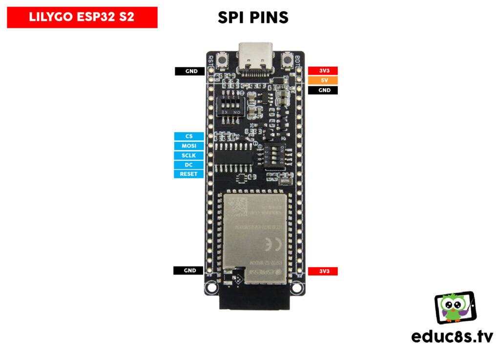
| Display Pins | Board Pins |
|---|---|
| VCC | 5V |
| GND | GND |
| CS | IO34 (CS) |
| RESET | IO38 (RESET) |
| A0 | IO37 (DC) |
| SDA | IO35 (MOSI) |
| SCK | IO36 (SCLK) |
| LED | 3.3V |
Connection
The first pin of the display is Vcc so we connect it to the 5V output of the board. The second pin is GND so we connect it to a GND pin of the board, I connected it to this GND pin. The third pin of the display is name CS. CS pin goes to the CS pin of the board which is the pin IO34. The next pin is RESET. Reset goes to the Reset Pin of the board which is pin IO38. The next pin of the display is A0. A0 goes to the DC pin of the board which pin IO37. The next pin is named SDA. SDA pin goes to the MOSI pin of the board which is pin IO35. The next pin is named SCK pin and we connect it to the SCLK pin of the board which is pin IO36. The last pin of the display is named LED and we connect it to a 3.3V output of the board.
That’s it. If we now power up the display, with a sample CircuitPython program already loaded in it we can see that the display works! The connection is ready. Let’s now go to the computer to see the software we need to make this display work.
Software
First of all, we need CircuitPython installed on the board. If you haven’t already installed CircuitPython on the board please watch the detailed video I have prepared about the procedure. You can watch that video by clicking on the card that will appear on the screen. Next, we need to install some libraries for the display.
Adafruit, the company that is developing CircuitPython has developed hundreds of libraries for displays, sensors and so on and they have packaged them all together in this Adafruit CircuitPython Bundle.zip file. All we have to do is to download this file on our computer and unzip it somewhere. Now, inside the folder we have to locate two libraries in order to be able to run the scripts I have developed. First of all, we need a library for the display. Under the lib folder we have to select the adafruit_ST7735r file. Be careful, there is also an adafruit_ST7735 library which won’t work with this display. We need the r version. Now we copy and paste this file inside the lib folder in the disk drive that appears when we connect the board to the computer, like this. Now we have to copy one more helper library using the same procedure. We need to locate the adafruit_display_text folder and copy and paste it in the lib folder of the board as we did before. This library will help us display text on the display.
Now we are ready to use the display. I use Thonny as the development environment at this moment. In order to use the board, we have to go to Tools – > Options –> Interpreter, select CircuitPython generic as the interpreter and select the port our board is connected to.
Now we are ready to write our code in this window, and then press the Run Button here and the board will execute it at once since CircuitPython is an interpreted language.
I have developed two simple programs to test the display. The first one displays a colored frame and a text on the display.
The second program loads 4 bitmaps that are stored on the board as you can see, and displays them one after another. I just wanted to check how fast it can update the whole screen. As you can see the display is pretty fast! Cool! As always you can find the code of both projects in the video description.
Conclusion
Now that we know how to use the ST7735 display with the ESP 32 S2 using CircuitPython we have a very powerful and inexpensive platform for future projects. Let’s see what kind of projects we can build with it. Thanks for watching, I will see you next time!
Leave A Comment