Hey guys, welcome to today’s tutorial. Today we are going to learn how to use the large 20×4 character LCD display with Arduino.
Intro to the Arduino 20×4 Character LCD Tutorial
I first came across the 20×4 LCD display a few weeks back on banggood.com and I was attracted to it because of its cheap price, size and the fact that it uses I2C communication protocol which means it only requires 2 pins(Asides VCC and GND) to communicate with the Arduino.
Today, we are going learn how to use these cheap character LCD display with Arduino and in the process of learning, we will build a simple real-time clock using the display, an Arduino, and the DS3231 RTC module.
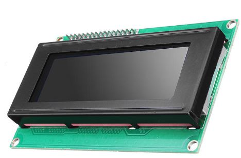
20×4 Character LCD
Different projects will require a different type of displays and I am sure at the end of this tutorial, this will be a great addition to the number of displays you are already familiar with.
Required Parts and Where to Buy
The following parts are required to build this project and they can each be bought through the link in front of them.
- Arduino Uno: https://educ8s.tv/part/ArduinoUno
- 20×4 LCD: https://educ8s.tv/part/20x4LCD
- DS3231 RTC: https://educ8s.tv/part/DS3231
- Small Breadboard: https://educ8s.tv/part/SmallBreadboard
- Jumper Wires: https://educ8s.tv/part/JumperWires
- Wires: https://educ8s.tv/part/Wires
- Power Bank: https://educ8s.tv/part/Powerbank
Full disclosure: All of the links above are affiliate links. I get a small percentage of each sale they generate. Thank you for your support!
[adsense]
Schematics
As mentioned earlier, the connection of this display is quite simple as it only requires two pins asides the VCC and GND pins. We have also covered using the DS3231 RTC module in several tutorials and you can check them out to understand the module the more but its connection to the Arduino is also described here. Connect the components as shown in the schematics below.
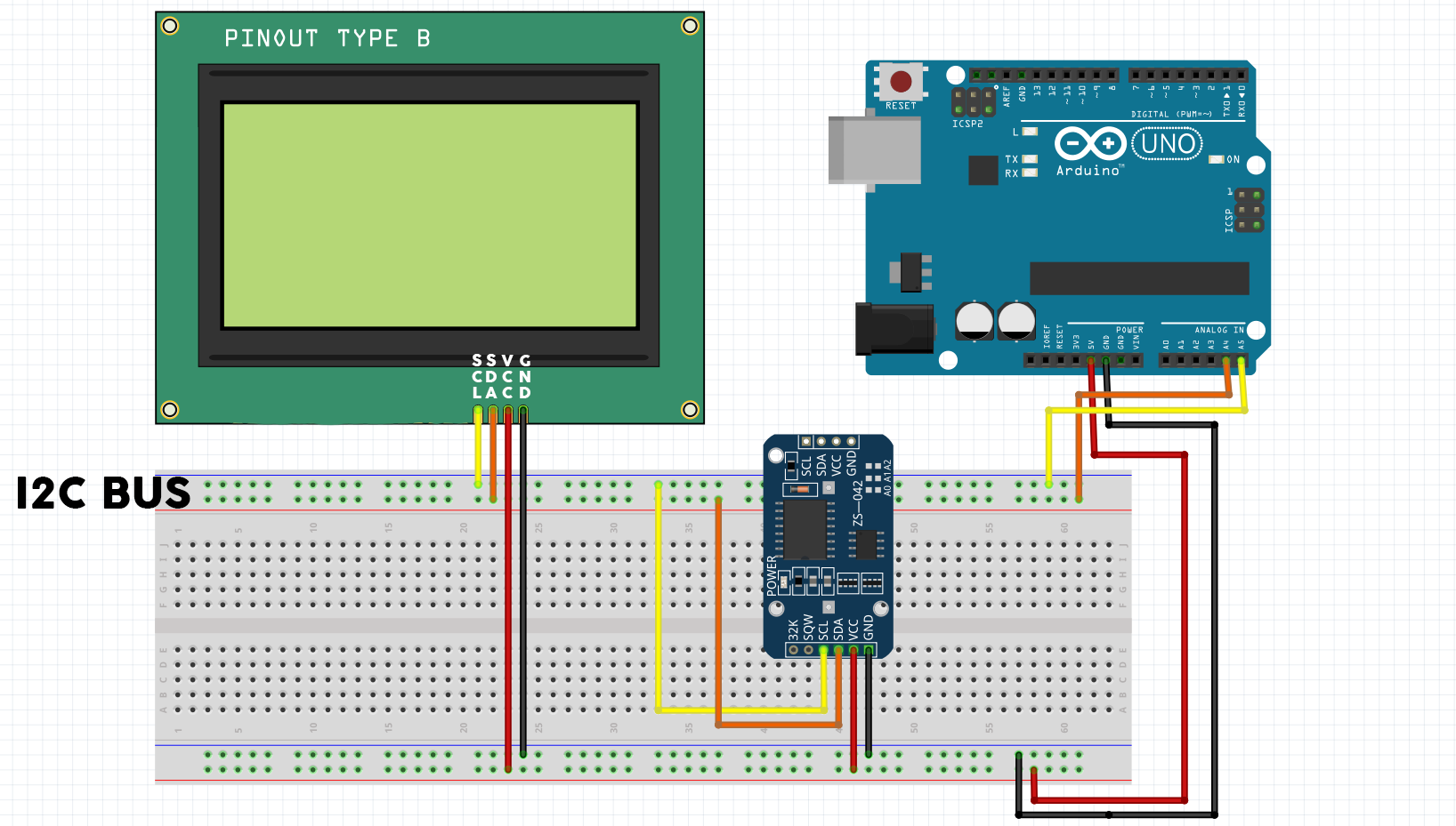
Schematics
The LCD and the DS3231 both communicate via I2C so they were both connected to the I2C bus of the Arduino.
To make the connection easier, here is a pin map.
LCD – Arduino
VCC ▶ 5v
GND ▶ GND
SDA ▶ SDA
SCL ▶ SCL
The DS3231 is connected the same way to the Arduino.
Code
We are going to write two simple sketches for this project. The first one will be to display a simple text on the display and the second one will be to use the display alongside the DS3231 and display date and time information from the display. To be able to work with this display easily, we will be using the NewLiquidCrystalLibrary and the DS1307 library for the RTC. The two libraries can be downloaded from the link below.
Libraries
? New LiquidCrystal: https://github.com/mlinares1998/NewLiquidCrystal
? DS1307 Library: https://github.com/PaulStoffregen/DS1307RTC
With the libraries downloaded and installed, we can now proceed to the codes.
The first one we write is the example code to display random text on the LCD.
We start the code by including the libraries needed after which we create an object of the LCD library.
#include <Wire.h>
#include <LiquidCrystal_I2C.h>

LiquidCrystal_I2C lcd(0x27, 2, 1, 0, 4, 5, 6, 7, 3, POSITIVE);  // Set the LCD I2C address
We then move to the void setup function where we initialize the display, set the cursor to the desired position where we want the text to start from and display the “hello youtube text”.
void setup()
{
  lcd.begin(20,4);
  lcd.setCursor(3,0);
  lcd.print("Hello YouTube!");
  lcd.setCursor(8,1);
  lcd.print("****");
  lcd.setCursor(0,2);
  lcd.print("This is a demo text");
  lcd.setCursor(8,3);
  lcd.print("****");
}
This example is actually to demonstrate how to print on all the four lines of the display using the set cursor function. The function takes in two arguments; the first one is used to specify the column on which the text to be displayed is to start from and the second argument is used to specify the rows.
The void loop is left blank since it must be included and we don’t want anything done there.
void loop()
{
}
The second Sketch is more complicated than the first as we now have to include the code to get time and date information from the RTC and display on the LCD.
As usual, we start by including the needed libraries. This time we will be using an additional library for the Real-time clock module which is the excellent DS1307RTC library which works for the DS3231 real-time clock too.
#include <Wire.h>
#include <LiquidCrystal_I2C.h>
#include <DS1307RTC.h>
Next, we create an object of the LCD library and also create some special characters which will be used to make the UI of the clock more friendly. You can play around and experiment with the UI.
LiquidCrystal_I2C lcd(0x27, 2, 1, 0, 4, 5, 6, 7, 3, POSITIVE);  // Set the LCD I2C address

byte verticalLine[8] = {
  B00100,
  B00100,
  B00100,
  B00100,
  B00100,
  B00100,
  B00100,
  B00100
};

byte char2[8] = {
  B00000,
  B00000,
  B00000,
  B11100,
  B00100,
  B00100,
  B00100,
  B00100
};

byte char1[8] = {
  0b00000,
  0b00000,
  0b00000,
  0b00111,
  0b00100,
  0b00100,
  0b00100,
  0b00100
};

byte char3[8] = {
  0b00100,
  0b00100,
  0b00100,
  0b00111,
  0b00000,
  0b00000,
  0b00000,
  0b00000
};

byte char4[8] = {
  0b00100,
  0b00100,
  0b00100,
  0b11100,
  0b00000,
  0b00000,
  0b00000,
  0b00000
};
With that done, we write the void setup() function. here, we initialize the LCD and create the custom characters after which we display the frame(UI) using the characters. You can always create your own custom character using the createChar function. After creating the characters, they are displayed on the LCD using the LCD.write(‘character index’) function.
void setup()
{
  lcd.begin(20,4);

  createCustomCharacters();

  printFrame();
}
The void loop() function for this project, is simplified using functions. Every second, we get the date and time data from the Real Time Clock and we print it on the display using the LCD.print command.
void loop()
{
   tmElements_t tm;

  if (RTC.read(tm)) {
    printDate(5,1,tm);
    printTime(6,2,tm);

  } else {
    if (RTC.chipPresent()) {

    } else {

    }
    delay(9000);
  }
  delay(1000);
}
If the time on the display is not correct, it can be corrected by uploading the setTime example to change the time on the Real Time Clock. The example can be accessed by following this file path. go to File -> Examples -> DS1307RTC and load the SetTime example. The program will get the time from your computer and it will set the time on the DS3231 module.
The complete versions of both sketch and the schematics can be downloaded via the link below.
——————–
CODE OF THE PROJECT & SCHEMATIC
——————–
Upload the code to your Arduino board, don’t forget to set the time if it’s not correct. You should see the time and date come up on the display as shown in the Image below.
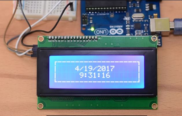
Demo
That’s it for this tutorial guys, thanks for reading and or watching. Do not hesitate to drop any question or comment you might have as regards the project in the comment section. I will be glad to respond to them. You can subscribe to our youtube channel by clicking the subscribe button below. This will ensure you never miss any new video or tutorial.
——————–
SUBSCRIBE ON YOUTUBE
——————–
Never miss a video: Subscribe to educ8s.tv
Dear Nick please if you can provide this for an Teensy 3.6 I use only Teensy board instead of Arduino.
The Arduino Uno are much to slow for my jobs and I2C for displays are very easy.
If you can find any time … please.
Thanks for all your video’s I enjoy this very much, great work.
Best regards,
Johan
Using a Teensy with this is very similar. You only need to find which pins are the SDA and SCL on the Teensy. Also, provide 5V to the display because I think Teensy is a 3.3V device.
Dear Nick, perhaps you can give a brilliant tip: below works fine.. only I need the lcd.print command how I do that. My ready programs use only lcd.print();
I use a Oled display type NHD-0420CW-AB3 works …fine. How I can use lcd.print etc.
Thanks in advance.
Johan
/*
Example sketch to display Strings and float values on the OLED
1602 display from Wide.HK. This uses a Lbrary that I’ve
put together containing some basic functions.
The I2C Address is set to 0x3C in OLedI2C.cpp
Phil Grant 2013 http://www.gadjet.co.uk 07/11/13
*/
#include “Wire.h”
#include “OLedI2C.h”
OLedI2C LCD;
float digit; //Variable to hold sample temperature value
void setup()
{
Wire.begin();
LCD.init();
digit = 21.6; //This would normally be the float value returned from a temp sensor or other sensor
}
void loop()
{
LCD.sendString(” Temp”,0,0); //Now includes the cursor position data (col, row)
LCD.sendFloat(digit,5,2,7,0); //Send the float value to the display starting
//at col 7 row 1 with 5 digits and 2 decimal places
while(1);
}
‘POSITIVE’ is not defined…..?
Got the same ” ‘POSITIVE’ is not defined…..” statement and I’m new to this – trying to learn – But I’m really stuck with this one … Please help.
got the same thing
Change for LiquidCrystal_I2C lcd(0x27,20,4); Verified the address I2C, maybe is 0X3F. You can check the address with this code in th serial port.
#include
void setup()
{
Wire.begin();
Serial.begin(9600);
Serial.println(“\nI2C Scanner”);
}
void loop()
{
byte error, address;
int nDevices;
Serial.println(“Scanning…”);
nDevices = 0;
for(address = 1; address < 127; address++ )
{
// The i2c_scanner uses the return value of
// the Write.endTransmisstion to see if
// a device did acknowledge to the address.
Wire.beginTransmission(address);
error = Wire.endTransmission();
if (error == 0)
{
Serial.print("I2C device found at address 0x");
if (address<16)
Serial.print("0");
Serial.print(address,HEX);
Serial.println(" !");
nDevices++;
}
else if (error==4)
{
Serial.print("Unknow error at address 0x");
if (address<16)
Serial.print("0");
Serial.println(address,HEX);
}
}
if (nDevices == 0)
Serial.println("No I2C devices found\n");
else
Serial.println("done\n");
delay(5000); // wait 5 seconds for next scan
}
Hi, had same ” ‘POSITIVE’ is not defined…..” error.
I “deleted / shift out of library” the existing “LiquidCrystal_I2C” library, so only “C:\….\Arduino\libraries\Newliquidcrystal_1.3.5” exists. Than error disappers.
Hi
Great project , thanks for sharing….slight problem though after I have left it running overnight I have the display showing 6:34:069 the hundreds and tens units are showing the seconds correctly and the digits are changing correctly but where has the 9 come from ? FYI it doesn’t change
Iain Ross the 9 was probably left unchanged after the clock flipped over from 11:59:59, as all subsequent times have fewer than eight characters.
Do you know if this LCD library will work with the Seeeduino Xiao?
Thank you.
I can only use the I2C_LCD library.