In this video we are going to see how to make Arduino power off itself with the help of a simple circuit! Let’s start!
If you have watched some of my previous videos you will know that I like my projects to have minimal power consumption so that we can use them with batteries for a long period of time. One of the biggest disadvantages of the Arduino boards is that they need a lot of current even when in idle state. This Arduino Uno board for example needs about 40mA when idle and about 20mA if we put the Atmega chip to sleep. That’s a lot of power, so, it will deplete any battery in a few days. So, I wanted a circuit that will let Arduino to turn off itself instead of putting it to sleep in order to conserve power. After a lot of experimentation and googling I finished a first basic version of this circuit. Let’s see it action.
I have an Arduino Uno board here which is battery powered. When I press the button, the Arduino turns on, drives this OLED display, and all it does is to count down to its automatic power off. After 5 seconds it will turn itself off! If I press the button again, the procedure starts over again! Great isn’t it! If I connect a Multimeter you can see that when Arduino is on, it draws around 50mA of current, and when it is off the circuit needs around 0.5mA! That means that we can expand the battery life of the project to months instead of days! You can keep your Arduino on for as long as you wish, and then when it has completed its job you can turn it off automatically. But let’s now see how to build this circuit.
——————–
WHERE TO BUY
——————–
1. Arduino Uno: https://educ8s.tv/part/ArduinoUno
2. OLED display: https://educ8s.tv/part/OLED096
3. MOSFET: http://bit.ly/30N06L
4. Push Buttons: https://educ8s.tv/part/Buttons
5. Small Breadboard: https://educ8s.tv/part/SmallBreadboard
6. Multimeter: https://educ8s.tv/part/Multimeter
7. Wires: https://educ8s.tv/part/Wires
8. Battery holder: https://educ8s.tv/part/BatteryHolderAA
9. Jumper wires: https://educ8s.tv/part/JumperWires
10. Resistors: https://educ8s.tv/part/Resistors
The heart of the circuit is this MOSFET which is a transistor. It works like a digital switch. If we apply 5V at its gate, it will allow a large amount of current to flow from the source pin to the drain pin. If there is no Voltage to the gate pin of the MOSFET, no current will flow from source to drain pins of the MOSFET. We are going to use this feature to control the Arduino board.
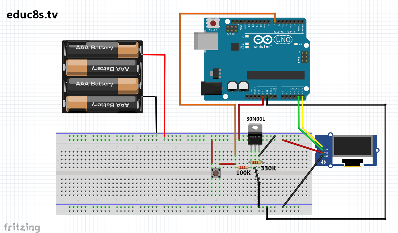
At first we place all the parts on the breadboard. We place the 330K resistor between the gate and the source of the MOSFET. Next we connect Vcc from the OLED display and one leg of the button to the positive rail of the breadboard. The next step is to connect the source pin of the MOSFET to the Ground rail of the breadboard. Next we connect the middle pin of the MOSFET and the GND from the display to one of the bottom rails of the breadboard. The next step is to connect the 100K resistor to the gate pin of the MOSFET. The other end of the resistor is connected to Digital Pin 7 of the Arduino and the other leg of the button. Now all we have to do, is to connect the OLED display to the I2C pins of the Arduino. SDA pin goes to analog pin 4 and SCL to analog pin 5. We then connect the positive rail of the breadboard to Arduino 5V and the bottom rail to Arduino GND. That’s it, we can now connect power to the upper breadboard rail and check if everything is working as expected! Great, you can find the schematic diagram of the circuit in a link in the description of the video.
[adsense]——————–
CODE OF THE PROJECT
——————–
——————–
SUBSCRIBE TO YOUTUBE
——————–
Never miss a video: Subscribe to educ8s.tv
hi,
I built a circuit like yours.
Here is the schem http://i.imgur.com/2vKAWa8.jpg
In OFF state (Arduino pin LOW), LEDs on Arduino board are dimmed (it is not switched off completely).
Do you know what is the reason?
Hello Michal, I somehow missed your comment. Try different resistor values for the MOSFET.
This _cannot_ be fixed by changing the resistors.
The circuit presented here is fundamentally unworkable, only _two_ transistors or a multi stage IC or fully isolated switch will work.
Don’t work? A multimeter can’t lie.
Explain
I tried 2 tranasistors (in case of failure of one of theme) and still the same
Did you ever find the reason ?
I’d say the 330K resistor is sinking enough current back to ground to still partially drive the LED, try turning off the circuit by switching the pin that’s connected to that resistor to be an input.
Please consider taking down this page, as you are confusing people by presenting a circuit which is fundamentally unworkable, and no change of resistor values will fix it.
Any modern IC has protection diodes between the I/O pins and supply rails, and these will create a current leakage path via your pulling resistor that partially powers the device. Lowering the resistor value will make the device be even more powered, while increasing it will increase the voltage drop across due to the current leaking through the device, and cause the FET itself to be partially turned on.
To make a circuit that works, you must use two FETs on controlling the other, or else an IC switch, either a high side switch enabled by a high signal, or a low side switch enabled by a low signal.
I have designed a system, seems it’s betters than Nick’s. Actually it’s my FIRST design, so I hope to be correct. I have tested it with simulator because I don’t have P – Channel mosfet to test it live. I will order soon.
Nick please test it!!! Keep it up!! The design http://prntscr.com/ilm03g
Can you suggest me LOW POWER (leak) mosfets (both types)?
Also the reason that I designed the above circuit is because I have tested your circuit and actualy works but
When the button is not pressed (arduino is off) between GATE-DRAIN there is voltge arround 1.4V.
I have not used so big values resistors that’s maybe the problem but seems the leakage will not be avoided.
The second reason is because I cound’t get the state of button to used it as power off. In your example it power offs based on time, but it would be great to create a video with SINGLE button to have power on/off like phones/computers/etc…
,t click that button