Hi guys, welcome to today’s tutorial. Today, we will look at how to use the soil moisture sensor with the Arduino.
Soil moisture sensor is a sensor used to measure the amount of water in the soil at any particular point in time. Instead of the old gravimetric method of measuring soil water content, the soil moisture sensor measures the volumetric water content indirectly by using other properties associated with the soil, like its electrical resistance to measure the soil humidity.
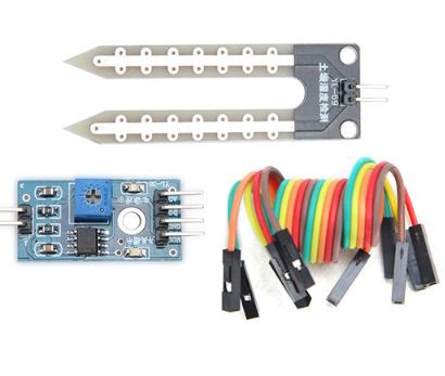
The soil humidity sensor used for this tutorial was acquired from banggood.com at a cheap price of less than $2. Some of the features of this sensor are listed below.
- Operating voltage: 3.3V~5V.
- Adjustable sensitivity (shown in blue digital potentiometer adjustment)
- Dual output mode, analog output more accurate.
- A fixed bolt hole for easy installation.
- With power indicator (red) and digital switching output indicator (green).
- Having LM393 comparator chip, stable.
- Panel PCB Dimension: 3cm x 1.5cm.
- Soil Probe Dimension: 6cm x 2cm.
- Cable Length: 21cm.
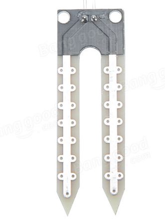
Soil moisture Sensor Probe
The probe of the sensor which is shown in the image below has two large exposed pads.
The more water in the soil the better the electrical conductivity between the pads as a result of lower resistance. when the soil is dry, the resistance in the soil becomes higher and conductivity between this pads reduces. This helps the sensor determine the water level in the soil.
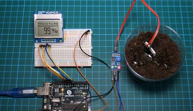
To make the reading of the soil humidity easy, we will be using the Nokia 5110 LCD display alongside with the Arduino.
At the end of this tutorial, we would have learned how to use the soil humidity sensor to read the soil humidity and display the humidity on an LCD. This project is a good building block for the development of an automatic irrigation system.
Required Parts and Where to Buy
The following parts are needed to build this project and they can be bought via the link in front of them.
- Soil Moisture Sensor: https://educ8s.tv/part/SoilMoistureSensor
- Cheap Arduino Uno: https://educ8s.tv/part/ArduinoUno
- Nokia 5110 LCD: https://educ8s.tv/part/NOKIA5110
- Small Breadboard: https://educ8s.tv/part/SmallBreadboard
- Jumper wires: https://educ8s.tv/part/JumperWires
- Wires: https://educ8s.tv/part/Wires
Schematics
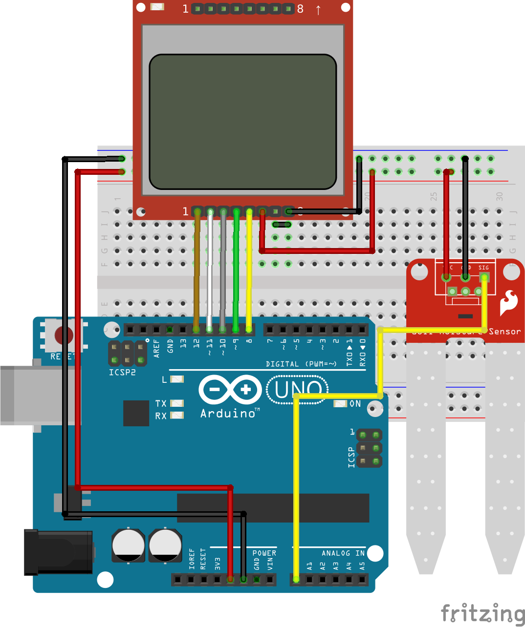
The schematic for this project is a fairly easy to replicate one. we have covered connecting the Nokia 5110 LCD to the Arduino in previous tutorials, one of which can be found via this link(). The soil sensor has just three pins which are VCC, GND, and SIG(signal) pin and they are connected to the Arduino as shown in the schematics below.
Schematics
The connections are further highlighted below.
Soil moisture Sensor – Arduino
VCC – 5V
GND – GND
SIG – A0
With everything connected, we can now move to the code for the project.
Code
Two Arduino code sketches are available for this tutorial. The first one is for those who do not have the Nokia 5110 LCD display while the second one is for those who have the LCD. The first sketch which does not incoporate the display uses the serial monitor as a means of displaying the data to make the changes in the sensor readings visible to the user.
Since the code sketches are similar and we have covered the how to use the Nokia 5110 LCD in more than 10 tutorials on this website, I will use the first code without the display as a reference point. I will advise that beginners go through the several Nokia 5110 LCD tutorials as they may learn one or two new tricks on using the display.
The concept behind the code is simple, we know the range of the arduino ADC is between 0 and 1023 so we read the analog value provided by the soil moisture sensor then using the range of the ADC, we convert the value to a percentage so it is easier for the user to understand and we display that percentage on the serial monitor (or on the Nokia 5110 LCD).
To explain the code briefly, the first thing we do is specify the analog pin of the Arduino to which the sensor is connected after which we create certain variables which will be used later on.
//////////////////////////////////////////////
  //        ARDUINO SOIL MOISTURE DEMO        //
 //                                          //
//           https://educ8s.tv           //
/////////////////////////////////////////////


int sensorPin = A0;
int sensorValue = 0;
int percent = 0;
With that done, we move to the void setup function where we initialize serial communication so our data can be displayed on the serial monitor later.
void setup() {
  Serial.begin(9600);
}
Next, is the void loop function where all the major action takes place. The first line of code under the function reads the analog value from the soil moisture sensor after which we call the convert to percent function which returns the percentage of water left in the soil as mentioned earlier. The percentage value is then displayed on the serial monitor using the printValueToSerial() function. The program is paused for 1000 ms and restarted again from the top.
void loop() {

  sensorValue = analogRead(sensorPin);
  percent = convertToPercent(sensorValue);
  printValuesToSerial();
  delay(1000);
}
The complete version of both the sketch with no provision for the LCD and the one with provision for the LCD can be downloaded via the link below.
To test the project, upload the code to your Arduino board and set up the system, inserting the sensor into a dry soil as shown in the image below.
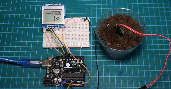
When the Arduino is powered, the since the soil is dry and the sensor does not detect any moisture, as seen in the image above, the percentage value will reduce to as low as 1%. If we decide to add a little amount of water to the soil so it becomes moist, as shown in the image below, the percentage soil humidity increases.
As mentioned at the beginning of this tutorial, it is just to show us how the sensor works. I will be making a tutorial on a more useful application of this sensor very soon. If you have comments and suggestions on cool projects you will like me to build with this sensor, kindly drop a comment under the comment section of this post.
Thanks for reading and watching. Don’t forget to subscribe so you don’t miss subsequent tutorials.
——————–
SUBSCRIBE ON YOUTUBE
——————–
Never miss a video: Subscribe to educ8s.tv
Hey nice tutorial, I need some help with a TFT lcd I got the Values and stuff right.
But somehow it overlaps my text. my code is below.
#include // Graphics library
#include // Hardware library
#include
int soil_sensor = A5;
int sensorValue = 0;
int percent = 0;
#define LCD_CS A3
#define LCD_CD A2
#define LCD_WR A1
#define LCD_RD A0
#define LCD_RESET A4
#define BLACK 0x0000
#define BLUE 0x001F
#define RED 0xF800
#define GREEN 0x07E0
#define CYAN 0x07FF
#define MAGENTA 0xF81F
#define YELLOW 0xFFE0
#define WHITE 0xFFFF
Adafruit_TFTLCD tft(LCD_CS, LCD_CD, LCD_WR, LCD_RD, LCD_RESET);
// — Setup
void setup(void) {
Serial.begin(9600);
tft.reset();
tft.begin(0x9341); // SDFP5408
tft.setRotation(0); // Need for the Mega, please changed for your choice or rotation initial
Serial.println(testText());
Serial.println(sensorValue);
Serial.println (percent);
delay(3000);
}
void loop(void) {
sensorValue = analogRead (soil_sensor);
percent = convertToPercent(sensorValue);
printValuesToSerial();
tft.setCursor(0, 10);
for(uint8_t rotation=0; rotation<1; rotation++) {
tft.setRotation(rotation);
delay(1000);
}
}
unsigned long testText() {
tft.setRotation(0);
tft.fillScreen(CYAN);
tft.setTextColor(BLACK);
tft.setTextSize(3);
tft.setCursor(0, 10);
delay(1000);
}
int convertToPercent(int value)
{
int percentValue = 0;
percentValue = map(value, 1023, 465, 0, 100);
return percentValue;
}
void printValuesToSerial()
{
tft.print("\n\nMoisture: ");
tft.print(sensorValue);
tft.print("\nPercent: ");
tft.print(percent);
tft.print("%");
}
hey, I am working with spi/TFT display 128*128 with a soil moisture sensor can you help me configure this.
I have built this together with an automatic watering system, However I get very short lifetime on the soil sensor, after about two weeks the sensor is “rusted” away and I get strange values. Am I doing something wrong here?
no its fine but most sensors destroy them selfs after time there’s a solution here https://www.youtube.com/watch?v=udmJyncDvw0
error in compiling. can somebody help me? thanks. my Nokia 5110 isn’t working.
how does map works?
CODE ISNT COMPAILING,
Code is not working
What error message do you get?
The reference to the Rinky Dinky web site you mention, notes that the operating voltage for the 5110 device is 3.3V with a maximum backlight voltage of 3.7V. How are you operating at 5V? Just luck?
My code is compiling OK, but I think long term usage at 5V could be short lived?
hello, plz i want to help me, so i need datasheet of MH-sensor-series for my objectif. if that possible send me soon.