Hello guys, Nick again, welcome to educ8s.tv, a channel dedicated to DIY electronics projects with Arduino, Raspberry Pi, ESP8266 and other popular boards.
Today we are going to be creating a rotary encoder controlled menu on a Nokia 5110 LCD display. Let’s get started!
In today’s tutorial, we are going learn how to build our own menu for the popular Nokia 5110 LCD display, in order to make our projects more user-friendly and infuse it with more capabilities. We have built a similar project in the past, but a lot of our viewers suggested that I should prepare another video on this subject so here it is.
The last time out, we used pushbuttons to navigate through the menu, but today, we will be using the rotary encoder to navigate through the menu. We will also be adding more options to the menu from the previous tutorial to enable us fully explore the ability of the rotary encoder to serve as a navigation tool.
A rotary encoder is an electro-mechanical device which converts the angular position or rotation of its shaft or axle to an analog or digital signal. They are used in several systems where precision and feedback in terms of rotational motion or angular position are required. Another good feature of the rotary encoder which will come in handy for this tutorial is that they come with buttons attached, so it can be clicked by pressing the nob and it will be recognized by the Arduino just as it will if it were any other button or switch.
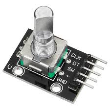
Rotary Encoder
To demonstrate the Arduino rotary encoder menu, we will be creating a simple menu which is displayed on the Nokia 5110 LCD display when the project is powered and with the rotary encoder, we will be able to navigate up or down the menu, selecting a menu option by pressing the rotary encoder button. The menu has 6 items, and as we navigate and select each item, the display will change accordingly. Sound’s exciting then let’s build.
Required Components and Where to Buy
The following components/parts are required to build this project and they can be bought through the link in front of each component.
1. Arduino Uno ▶ https://educ8s.tv/part/ArduinoUno
2. Rotary Encoder ▶ https://educ8s.tv/part/RotaryEncoder
3. Nokia 5110 LCD ▶ https://educ8s.tv/part/NOKIA5110
4. Small Breadboard ▶ https://educ8s.tv/part/SmallBreadboard
5. Jumper Wires ▶ https://educ8s.tv/part/JumperWires
6. Wires ▶ https://educ8s.tv/part/Wires
7. Power Bank ▶ https://educ8s.tv/part/Powerbank
Full disclosure: All of the links above are affiliate links. I get a small percentage of each sale they generate. Thank you for your support!
[adsense]
Schematics
Connect the components/parts as shown in the schematics below.
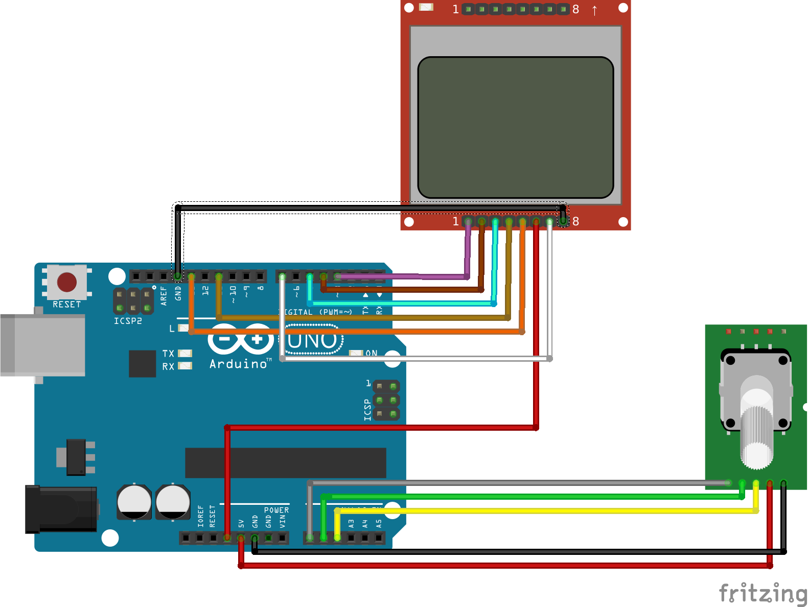
Schematics
To simplify the schematics further, the pin connection between the components is described below.
LCD ▶ Arduino
Reset ▶ D3

pin2 ▶ D4

pin3 ▶ D5

pin4 ▶ D11

pin5 ▶ D13

VCC ▶ 3.3v

Backlight ▶ D7

GND ▶ GND


Rotary Encoder ▶ Arduino

GND ▶ GND

VCC  ▶ VCC

SW ▶  A2

DT ▶ A1

CLK ▶ A0
Connect the components as described and double check your connections to make sure there is no mistake.
Code
The code of the project is complex but I will do my best to explain it. You will get a basic understanding of how the code works but to totally grab it, I will advise you try creating your own menu and see exactly how it works.
To implement this project, we will be using 4 libraries. Two out of the four libraries will be used for the display, and the remaining two will be used to interface with the rotary encoder.
LIBRARIES
? Adafruit GFX: https://github.com/adafruit/Adafruit-GFX-Library
? Nokia 5110: https://github.com/adafruit/Adafruit-PCD8544-Nokia-5110-LCD-library
? Encoder Library: https://github.com/0xPIT/encoder/tree/arduino
? TimerOne library: https://github.com/PaulStoffregen/TimerOne
To briefly explain the code;
The first thing we do is include the libraries we will be using for the project.
//////////////////////////////////////////////
  //       Arduino Rotary Encoder Menu        //
 //                 v1.0                     //
//           http://www.educ8s.tv           //
/////////////////////////////////////////////

#include <Adafruit_GFX.h>
#include <Adafruit_PCD8544.h>
#include <ClickEncoder.h>
#include <TimerOne.h>
Next, we create variables to hold the menus after which we create an object of the click encoder and the LCD library.
int menuitem = 1;
int frame = 1;
int page = 1;
int lastMenuItem = 1;

String menuItem1 = "Contrast";
String menuItem2 = "Volume";
String menuItem3 = "Language";
String menuItem4 = "Difficulty";
String menuItem5 = "Light: ON";
String menuItem6 = "Reset";

boolean backlight = true;
int contrast=60;
int volume = 50;

String language[3] = { "EN", "ES", "EL" };
int selectedLanguage = 0;

String difficulty[2] = { "EASY", "HARD" };
int selectedDifficulty = 0;

boolean up = false;
boolean down = false;
boolean middle = false;

ClickEncoder *encoder;
int16_t last, value;

Adafruit_PCD8544 display = Adafruit_PCD8544( 5, 4, 3); //Download the latest Adafruit Library in order to use this constructor
Next, we write the void setup function. The void setup function contains the code used to initialize our screen and the rotary encoder setting it to start at zero. We also created an interrupt routine which will be used to detect button press during within any of the menu pages.
void setup() {

  pinMode(7,OUTPUT);
  turnBacklightOn();

  encoder = new ClickEncoder(A1, A0, A2);
  encoder->setAccelerationEnabled(false);

  display.begin();
  display.clearDisplay();
  setContrast();

  Timer1.initialize(1000);
  Timer1.attachInterrupt(timerIsr);

  last = encoder->getValue();
}
With the void setup() all done, we proceed to write the void loop function which is the one with some level of complexity. The function basically creates the menu and uses the variables created initially to keep track of the previous, current and next state so when the rotary encoder is turned, it knows the right menu to display. The menu selection part of the code is also handled by a routine within the void loop() function.
The complete code for this project (Arduino Rotary Encoder Menu.) can be downloaded by clicking the link below.
CODE OF THE PROJECT
Upload the code to your Arduino board and you should see the display come up as shown in the image below.
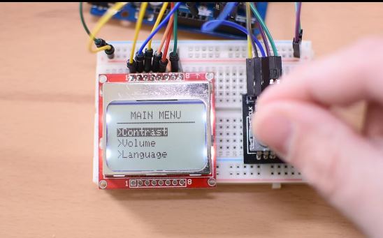
Demo
That’s it for this tutorial guys, thanks for watching/reading. As usual, feel free to reach out to me via comments should you get stuck with any of the steps, I will be glad to help. Also by subscribing, you get notified by youtube whenever we post a new tutorial video so please, subscribe.
——————–
SUBSCRIBE ON YOUTUBE
——————–
Never miss a video: Subscribe to educ8s.tv
Excuse me, but isn’t missing the link to the “CODE OF THE PROJECT & SCHEMATIC”?
You are right. I am going to fix it soon!
sir the link is broken. Thx
Yes, I am going to fix it soon!
Thx a lot , please do it very soon.
Done ;-)
Plus can you make a TFT gcode sender
Dear friend Nick, sorry to inform you that you’ve forgotten top put the link to your Arduino code.
You are right! I am going to upload it soon!
If you don’t already know it the code link has been fixed and the sketch is now available. It works great too!
I really appreciate the code, and the effort to share it in details!
I would like to ask you, about more simple code, with three option menu line, instead six.
Example: voltage, current and power ( Watts ).
Another question, how can I place some useful information from the ADC on the LCD?
Thank you,
Helcio
wonderful code sir can you please help with it.I want to make list within list.i.e. i want to display [EN ES EL ] in list form.All these three should be in one frame inside menu item.
Thank you sir.Hope to get reply soon
SHASHANK
Thank you!!! for sharing, what a nice project. I thinking introduce it to my project.
I have a question, how I can get some extra option:
1. How to setting hierarchy menu, eg. first start “welcome” page after second page where can be showing for eg.. visualization signal and if encoder is touch or click then start menu?
2. If no activity by 10sec. in menu, automatically go back to page with visualization?
I need just to know how to set up behavior menu.
Thank you
I’ll second Arkey comment. And how do you move the pins for the display, or assign them for use in a Nano with less than 13 pins? I didn’t see anything in the sketch for pins 11 and 13, I’m assuming This Adafruit_PCD8544( 5, 4, 3) and this pinMode(7,OUTPUT) can be changed to change those wires locations, but stumped on pins 11 and 13.
Got the pins…. 11 and 13 are MISO and SCK, so they go to D12 and D13 on Nano.
Yeah! I rewrite it for oled 0.96 128×64 display + own startup logo and welcome text. Moreover I rewrite from beginning encoder and button. Now I didn’t need lib ClickEncoder and TomerOne and all working without problem and faster than original. My version had more options for button and encoder can be easy configurable in range -999 to 999 , can be setting just from 0-127 or anywhere as you like in main range. Also I added setup initial encoder value. Will be some more options. I will report here my progress and if someone wants get my code, I put it on GitHub if finished. Now mentioned option working nice without any problems.
I’m looking for this! Can you tell me how you achieved this?
Just I forgot, my project is for Teensy 3,2 but should be easy adaptatable for Arduino
That is amazing! i was wordering if it would be possible to port this menu to different displays..
I want it to work on a teensy 3.6 with a Teensyview (oled 128×32) or a Adafruit ssd1306 (oled 128×64) So i am really curios how you did it…
Hi. This is a great project. What is the purpose of String difficulty variables?
Is it possible to use this on a SSD1306 I2C OLED display? How to achieve this?
Were you able to achieve this?
I just want to give you some hopefully constructive criticism.
The first thing that I do when I downloads someone else’s code in order to learn from it is to go through it and edit the whole code so that it follows my preferred coding style, personally I prefer this:
if()
{
action();
}
as opposed to this(which I find to be much more unclear to read when there is a lot of if’s and else if’s):
if(){
action();
}
My criticism is about how you haven’t chosen a style but instead alternates between them, this might to some seem like a trivial and unimportant subject but I really do believe that the person whom chooses a particular style benefits from it but particularly in case a person is sharing he’s/her’s code with others then it makes the reading of the code much more pleasant if the code adheres to one coding style instead of two, it also minimizes the chance of errors on part of the reader.
I haven’t even begun yet to get to grips with your code so this is thus far all I wanted to say, thanks for sharing.
Regards
David
Hello David, thanks for the comment. You are right. Clean code and readable code is very important indeed. I try hard to write clean code, and I will continue to improve as time goes by. Thanks again.
Sorry Sir but your program is full with mistakes..
The Arduino can not translate it and it can not run..
I modified it but I think I have to check it from the first alphabet to the last..
Regards1
Janos
Where in the code can I re-assign the pin4 ▶ D11 and the pin5 ▶ D13 to pin6 > D11 and pin7 > D13?
Hi, many thanks for your video’s and projects they have been very helpful. I was wondering with this project I want to use two NRF24L01 modules for control on the other Arduino. How would this data in the menus be put into a data pipe to be sent across and then interpreted on the receiver side? I have watched your other tutorial on the NRF24L01 modules but I am battling on how to change the code for this project. If you could please help I would really appreciate it.
Can you make a new video on how to make the rotary encoder menu for 128×64 LCD. And it would be really helpful if you provide the codings.
Hello, Thank you for help me get started with this. What I need to know is the pin out for your 5110 , mine. is not the same. I know it works as I got the sparkfun tutorial going. My display’s pins are as follows, Pin 1 – VCC, 2 – GND, 3- SCE, 4 – RES, 5-d/C, 6 – SDIN, 7 – SCLK, 8 LED. You can see it on the sparkfun web site if you like. I just need the pic of the back of yours and I can translate them into mine and hopefully, it works.
Great piece of code. I had started to develop a menu system for the NOKIA but this saved me countless hours of frustation. In fact looking at your code I doubt that I could have achieved anything like it.
Buenas noches.
Estoy queriendo adaptar este codigo para NodeMCU, pero no compila. Podria darme una mano para poder ejecutarlo en ESP8266? Gracias
Hu,
Thanks for the code.
I modified the code to use it with a 0.96″ oled display.
I successfully did all the modifications but running into few visual glitches.
For example:
On my screen I can display only two menu items at once
So with that in mind can you point out where and what I’ll need to change in the existing code.