Hi guys, for today’s tutorial, we will take a look at building an RFID based project with an Arduino using the RC522 reader and writer. We will be learning about the Reader and how to use it with the Arduino.
For the first time on this website, we will be using the Arduino with RFID tags. Today’s project reads the Unique ID of each RFID tag we place close to the reader and displays it on the attached OLED display. If the UID of the tag is equal to a predefined value stored in the Arduino’s memory, then “Unlocked” is displayed on the OLED. If the UID of the card does not match the stored value, “LOCKED” is displayed.
For the first time, we are going to use RFID tags with Arduino. I have built a simple project which reads the Unique ID (UID) of each RFID tag we place it close to the reader and displays it on this OLED display. If the UID of the tag is equal to a predefined value that is stored in Arduino’s memory, then on the display we are going to see the “Unlocked” message. If the Unique ID of the card is not equal to the predefined value, the Unlock message won’t appear.
How Do RFIDs work?
RFID stands for radio frequency identification system, The system is made up of readers(and Writers) and tags. The readers use electromagnetic fields to automatically identify and track electronically stored information contained in tags which are usually attached to objects that are described by the information.
RFID tags come in two forms, Active and passive. Passive tags collect are powered when needed by energy from a nearby RFID reader’s interrogating electromagnetic wave using the principle of electromagnetic induction. After being powered, the reader will then be able to get the information stored on it. All this is done within few seconds. Active tags on the other hand, have a local power source (such as a battery) and may operate hundreds of meters from the RFID reader. Unlike a barcode, the tag need not be within the line of sight of the reader, so it may be embedded in the tracked object.
Each RFID tag has a small chip inside. If a flashlight is placed under the RFID card, the small chip and the coil that surrounds it becomes visible. This chip stores the information on the card. In addition, each RFID tag has a unique number that identifies it which is known as the UID. Asides from the UID, each tag has the ability to some amount of data. The RFID tags used in this tutorial for instance can store up to 1Kb of data. We however won’t use this functionality today but will do so in a future video. Today, all we are interested in is to identify a specific card by its UID.
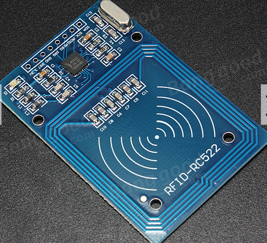
For this tutorial, we will be using the low cost, highly integrated reader/writer, and 13.56 MHz contactless communication enabled MFRC522 based RFID Reader Module due to the ease with which it can be used, its popularity and its low cost.
Some of the features of the reader/writer module are listed below.
Features:
- MFRC522 chip based board
- Operating frequency: 13.56MHz
- Supply Voltage: 3.3V
- Current: 13-26mA
- Read Range: Approx 3cm
- SPI Interface
- Max Data Transfer Rate: 10Mbit / s
- Dimensions: 60mm × 39mm
Required Components and Where to Buy
The following components are required to build this project and they can be bought via the link in front of them.
- Arduino Uno: https://educ8s.tv/part/ArduinoUno
- RFID module: https://educ8s.tv/part/RFID
- OLED display: https://educ8s.tv/part/OLED096
- Small Breadboard: https://educ8s.tv/part/SmallBreadboard
- Wires: https://educ8s.tv/part/Wires
- Power Bank: https://educ8s.tv/part/Powerbank
Full disclosure: All of the links above are affiliate links. I get a small percentage of each sale they generate. Thank you for your support!
[adsense]Arduino RFID tutorial – The connection
The schematics for this project is quite simple as we only need to connect two other components to the Arduino.
Connect the components as shown in the schematics below.
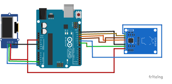
Schematics
The RFID reader module uses the SPI interface in order to communicate with Arduino. So we are going to use the hardware SPI pins of the Arduino UNO.
To make the connections easier to follow, the pin connections between other commpone
RST pin goes to digital pin 9. IRQ pin stays unconnected. MISO pin goes to digital pin 12. MOSI pin goes to digital pin 11. SCK pin goes to digital pin 13 and lastly SDA pin goes to digital pin 10. That’s it. The RFID reader is connected.
The pin connections between the Arduino and the other components are shown below to make the connections easier to follow.
The connection between the Arduino and the RC522 reader is described below;
RFID READER ▶ ARDUINO
SDA ▶ D10
SCK ▶ D13
MOSI ▶ D11
MISO ▶ D12
IRQ ▶ Not connected
GND▶ GND
RST ▶ D9
3.3V ▶ 3.3V
NOTE: Do not power the reader with 5V. You will fry the reader
The connection between the Arduino and the OLED Display is described below;
OLED ▶ Arduino
SCL ▶ A5
SDA ▶ A4
VCC ▶ 5v
GND ▶ GND
Arduino RFID tutorial – The code
In order to easily write the code for this project, we some libraries.
First of all we need the MFRC522 Rfid library. In order to install it, go to Sketch -> Include Libraries -> Manage libraries. Search for MFRC522 and install it.
We also need the Adafruit SSD1306 library and the Adafruit GFX library for the display. Install both libraries with the same procedure.
The Adafruit SSD1306 library needs a small modification. Go to the Arduino -> Libraries folder, open the Adafruit SSD1306 folder and edit the Adafruit_SSD1306.h library. Comment out line 70 of the .h file and uncomment line 69, by doing this we specify the resolution of our display which is 128×64.
With that done, we are now ready to write the code for this project.
As usual, we start by including the libraries that will be used for this project as shown below.
#include <MFRC522.h>
#include <Adafruit_GFX.h>
#include <Adafruit_SSD1306.h>
#include <SPI.h>
Next, we declare the pins of the Arduino to which the reader is connected and create an instance of the MFRC522 library.
#define OLED_RESET 4
Adafruit_SSD1306 display(OLED_RESET);
#define SS_PIN 10
#define RST_PIN 9
 MFRC522 rfid(SS_PIN, RST_PIN); // Instance of the MFRC522 library
Next, we declare the value (an array of integers) of the RFID tag that we want the Arduino to recognize.
int code[] = {69,141,8,136}; //This is the stored UID
int codeRead = 0;
String uidString;
Next, we write the void setup function where we initialize the RFID reader and the Display. Serial and SPI and I2C communications are also enabled as they all will be used for this project. Since the system is just starting up, it is set to go into lock mode, so lock is displayed on the Display.
void setup() {
   Serial.begin(9600);
  SPI.begin(); // Init SPI bus
  rfid.PCD_Init(); // Init MFRC522
  display.begin(SSD1306_SWITCHCAPVCC, 0x3C);  // initialize with the I2C addr 0x3D (for the 128x64)
 // Clear the buffer.
  display.clearDisplay();
  display.display();
  display.setTextColor(WHITE); // or BLACK);
  display.setTextSize(2);
  display.setCursor(10,0);
  display.print("RFID Lock");
  display.display();
  }
Next is the void loop function, the void loop function is written in such a way that the RFID reader checks for a tag every 100ms. The check is done by calling the readRFID() function.
void setup() {
   Serial.begin(9600);
  SPI.begin(); // Init SPI bus
  rfid.PCD_Init(); // Init MFRC522
  display.begin(SSD1306_SWITCHCAPVCC, 0x3C);  // initialize with the I2C addr 0x3D (for the 128x64)
 // Clear the buffer.
  display.clearDisplay();
  display.display();
  display.setTextColor(WHITE); // or BLACK);
  display.setTextSize(2);
  display.setCursor(10,0);
  display.print("RFID Lock");
  display.display();
  }
The readRFID() function works in such a way that If a tag is detected on the reader, the UID of that tag is printed on the display after which it is compared with the UID that is stored in the code variable. If the values match, “UNLOCK” message is displayed on the display, else, it will stay locked.
void readRFID()
{
 rfid.PICC_ReadCardSerial();
  Serial.print(F("\nPICC type: "));
  MFRC522::PICC_Type piccType = rfid.PICC_GetType(rfid.uid.sak);
  Serial.println(rfid.PICC_GetTypeName(piccType));

  // Check is the PICC of Classic MIFARE type
  if (piccType != MFRC522::PICC_TYPE_MIFARE_MINI &&
    piccType != MFRC522::PICC_TYPE_MIFARE_1K &&
    piccType != MFRC522::PICC_TYPE_MIFARE_4K) {
    Serial.println(F("Your tag is not of type MIFARE Classic."));
    return;
  }
   clearUID();
    Serial.println("Scanned PICC's UID:");
    printDec(rfid.uid.uidByte, rfid.uid.size);
   uidString = String(rfid.uid.uidByte[0])+" "+String(rfid.uid.uidByte[1])+"      "+String(rfid.uid.uidByte[2])+ " "+String(rfid.uid.uidByte[3]);
    printUID();
     int i = 0;
    boolean match = true;
    while(i<rfid.uid.size)
    {
      if(!(rfid.uid.uidByte[i] == code[i]))
      {
           match = false;
      }
      i++;
    }

    if(match)
    {
      Serial.println("\nI know this card!");
      printUnlockMessage();
    }else
    {
      Serial.println("\nUnknown Card");
    }
 // Halt PICC
  rfid.PICC_HaltA();
 // Stop encryption on PCD
  rfid.PCD_StopCrypto1();
}
Feel free to modify this code to store more than 1 UID values in order the project to recognize more RFID tags and do more cool stuffs.
The complete code for this project can be downloaded by clicking on the download link below.
——————–
CODE OF THE PROJECT
——————–
As you can see with a very low cost we can add an RFID reader to our projects. You can watch the youtube video above to see the system in action.
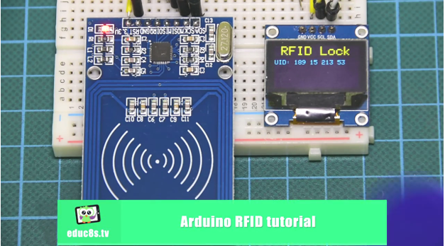
The RFID System in Action
We can easily build a security system and other useful and cool projects with a reader like the RC522. My main intention is to build some interactive games for kids using this RFID reader and a lot of RFID tags. In a future video we will also try to write and read data from an RFID tag. At this point I would love to hear your opinion about this RFID card reader. Do you plan to use it in any of your projects? Please post any comments or ideas in the comments section below, thanks!
——————–
SUBSCRIBE ON YOUTUBE
——————–
Never miss a video: Subscribe to educ8s.tv
Thanks I’ve been looking for this!
Hello, I try to upload this code to my Arduino UNO but I have a problem. The program send me a error, like this:
Arduino:1.8.4 (Mac OS X), Tarjeta:”Arduino/Genuino Uno”
El Sketch usa 16984 bytes (52%) del espacio de almacenamiento de programa. El máximo es 32256 bytes.
Las variables Globales usan 1181 bytes (57%) de la memoria dinámica, dejando 867 bytes para las variables locales. El máximo es 2048 bytes.
avrdude: stk500_recv(): programmer is not responding
avrdude: stk500_getsync() attempt 1 of 10: not in sync: resp=0x00
avrdude: stk500_recv(): programmer is not responding
avrdude: stk500_getsync() attempt 2 of 10: not in sync: resp=0x00
avrdude: stk500_recv(): programmer is not responding
avrdude: stk500_getsync() attempt 3 of 10: not in sync: resp=0x00
avrdude: stk500_recv(): programmer is not responding
avrdude: stk500_getsync() attempt 4 of 10: not in sync: resp=0x00
avrdude: stk500_recv(): programmer is not responding
avrdude: stk500_getsync() attempt 5 of 10: not in sync: resp=0x00
avrdude: stk500_recv(): programmer is not responding
avrdude: stk500_getsync() attempt 6 of 10: not in sync: resp=0x00
avrdude: stk500_recv(): programmer is not responding
avrdude: stk500_getsync() attempt 7 of 10: not in sync: resp=0x00
avrdude: stk500_recv(): programmer is not responding
avrdude: stk500_getsync() attempt 8 of 10: not in sync: resp=0x00
avrdude: stk500_recv(): programmer is not responding
avrdude: stk500_getsync() attempt 9 of 10: not in sync: resp=0x00
avrdude: stk500_recv(): programmer is not responding
avrdude: stk500_getsync() attempt 10 of 10: not in sync: resp=0x00
Problema subiendo a la placa. Visita http://www.arduino.cc/en/Guide/Troubleshooting#upload para sugerencias.
Este reporte podría tener más información con
“Mostrar salida detallada durante la compilación”
opción habilitada en Archivo -> Preferencias.
I´m not understand this, you can help me please?
I´m spaniard, I´m sorry for my bad English.
Thank you very much
Rx tx error replace crystal near microcontroller
int code[] = {69,141,8,136}; //This is the stored UID
how to add more UID?
How do you add more UID’s
int code[][4] = {{211,01,35,245}, {67,141,239,245}}
Sorry, int code[][2] = {{211,01,35,245}, {67,141,239,245}}